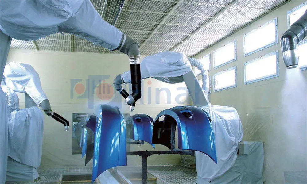
The ed coating process (electrodeposition coating) has become the global standard for applying highly uniform, corrosion‑protective primers – especially in the automotive industry. By using electrical current to deposit paint onto conductive surfaces, this method ensures complete coverage of complex geometries, including cavities and edges. This article provides a technical deep dive into the ed coating process, covering the electrochemical fundamentals, stage‑by‑stage workflow, critical equipment, common defects, and how suppliers like HANNA engineer robust e‑coat systems for high‑volume production.
Electrodeposition uses direct current to migrate charged paint particles (ionised polymer resins) toward a grounded metal part. Two main types exist: anodic (the part is the anode) and cathodic (the part is the cathode). Today, cathodic e‑coat dominates because of its superior corrosion protection – the deposited film is more resistant to saponification and alkali attack.
In a cathodic system, the part is connected to the negative terminal. Water electrolysis at the cathode generates hydroxyl ions (OH⁻), which locally raise the pH near the part surface. This causes the positively charged amine‑stabilised resin to coagulate and deposit as an insoluble film. Simultaneously, oxygen and hydrogen evolve at the anode (typically stainless steel electrodes in the tank). The deposition voltage usually ranges from 150 to 400 V, and the current density decreases as the insulating film builds – a self‑limiting action that produces uniform thickness even on recessed areas.
The e‑coat bath is a complex waterborne dispersion containing:
Resin (epoxy‑ or acrylic‑based) – provides film formation and corrosion resistance.
Pigment paste – contains colour pigments, extenders, and anti‑corrosion fillers.
Co‑solvents – improve flow and film coalescence.
Acids (e.g., acetic or lactic acid) – neutralise the resin to maintain water solubility.
Key process parameters that must be tightly controlled are: solids content (18–22 %), pigment‑to‑binder ratio, pH (typically 5.8–6.4 for cathodic systems), conductivity (1000–2000 µS/cm), and temperature (28–34 °C). Any drift can destabilise the bath or degrade film quality.
A complete ed coating process line consists of several consecutive stages, each essential for final quality.
Pretreatment – Cleaning and phosphating (or zirconium‑based conversion coating) to remove oil, rust, and to create a receptive surface. This stage directly affects adhesion and corrosion resistance.
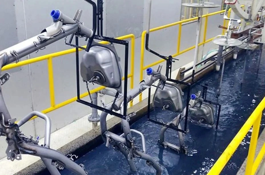
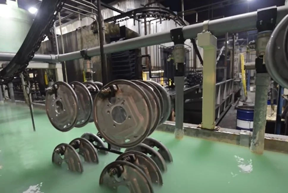
Electrodeposition tank – The part is immersed in the paint bath while DC voltage is applied. Dwell time (typically 2–3 minutes) determines film thickness, which usually ranges from 15 to 25 µm.
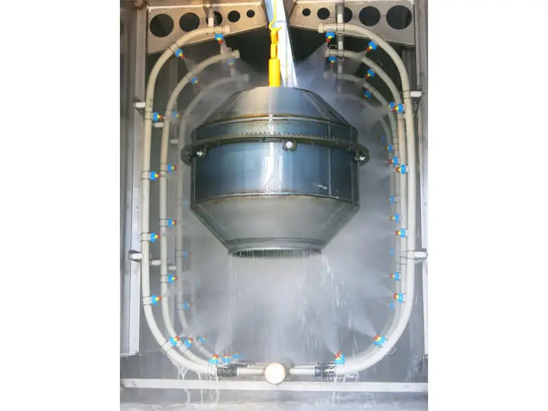
Post‑rinses – After exiting the tank, parts are spray‑rinsed with ultrafiltrate (permeate from the bath) to recover drag‑out paint and prevent surface defects. A final deionised water rinse avoids ionic contamination.
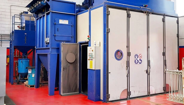
Curing oven – The wet film is baked at 160–180 °C for 20–30 minutes to crosslink the resin and develop full film properties.
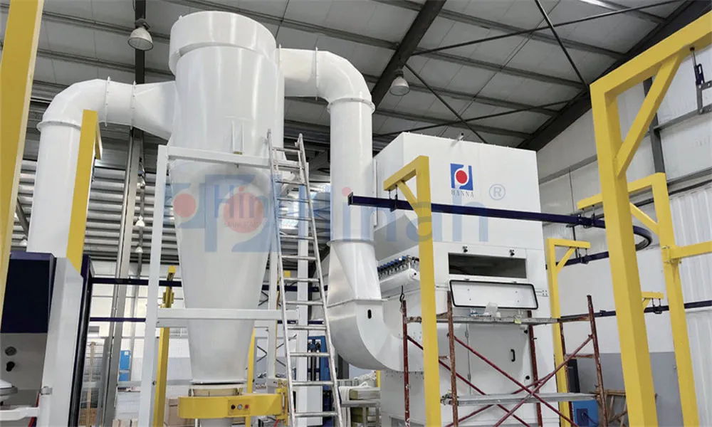
HANNA designs fully integrated e‑coat lines with precise control over each stage, ensuring consistent film build and minimal rejects.
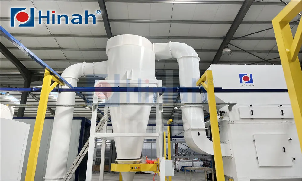
Reliable ed coating process equipment must handle high volumes, maintain bath stability, and minimise energy consumption.
Modern rectifiers provide DC output with programmable voltage ramps to avoid “burn‑off” at part entry. Pulse‑width modulation (PWM) technology improves efficiency and allows precise control of deposition voltage, which is critical for mixed‑metal assemblies.
E‑coat tanks are typically mild steel lined with glass flake vinyl ester or stainless steel. Circulation pumps (often centrifugal) keep the bath homogeneous and prevent pigment settling. Flow patterns must avoid dead zones; computational fluid dynamics (CFD) is now used to optimise nozzle placement and turnover rate (usually 4–6 tank volumes per hour).
UF membranes (spiral‑wound or tubular) continuously filter the bath, removing low‑molecular‑weight impurities (like salts from pretreatment carry‑over) and producing permeate for rinsing. A well‑designed UF system extends bath life and reduces paint consumption by recovering drag‑out.
E‑coat baths generate heat from pumping and electrical resistance during deposition. Plate‑and‑frame or shell‑and‑tube heat exchangers, fed by chilled water, maintain the set temperature. Redundant pumps and automatic bypass ensure reliability.
Even with excellent equipment, the ed coating process can experience defects. Below are common issues and their root causes.
Rough surface / “orange peel” – Often caused by high bath temperature, low solvent level, or excessive voltage.
Pinholes / craters – May result from gas entrapment (too high voltage ramp), contamination with oil or silicone, or insufficient surfactant.
Low film thickness – Check solids content, voltage, dwell time, or bath conductivity (too low).
Poor adhesion / blistering after cure – Usually linked to insufficient cleaning, incorrect phosphate coating, or under‑cure.
Bath instability (settling, pH drift) – Requires checking anolyte system operation, replenishment rates, and microbial growth (rare in fresh baths).
Regular analytical tests (non‑volatile matter, pigment‑to‑binder ratio, MEQ (milliequivalents) of acid) and scheduled anode cleaning are mandatory. HANNA provides training and remote monitoring packages to help customers maintain optimal bath conditions.
The ed coating process offers distinct benefits, but it is not a universal solution for every application.
Complete coverage of complex shapes, including box sections and cavities (“throwing power”).
High automation, low labour cost per part.
Excellent corrosion resistance (often 1000 h salt spray on treated steel).
Environmentally friendly – waterborne with high transfer efficiency (>95 %).
Only conductive substrates can be coated.
Film thickness is limited (typically ≤35 µm per coat).
Colour change is difficult – usually limited to black, grey, or a single colour per bath.
High initial capital investment for tanks, rectifiers, and UF systems.
While automotive body‑in‑white is the largest user of e‑coat, many other sectors rely on the ed coating process:
Agricultural and construction equipment – tractor parts, loader arms, and chassis benefit from the tough, corrosion‑resistant primer.
Appliances – washing machine cabinets, dryer drums, and refrigerator compressor housings are often e‑coated before topcoating.
Electrical enclosures – junction boxes, switchgear cabinets, and transformer tanks require long‑term rust protection.
Automotive components – coils, springs, brake parts, and small stampings are processed in bulk on conveyor lines.
Q1: What is the difference between anodic and cathodic
electrocoating?
A1: In anodic electrocoating, the part is the anode
and metal ions dissolve into the film, which can reduce corrosion resistance.
Cathodic electrocoating (the part is the cathode) deposits a more chemically
resistant film and is the dominant technology today for automotive and
industrial primers.
Q2: How is film thickness controlled in the ed coating
process?
A2: Film thickness is primarily determined by applied
voltage, dwell time, bath temperature, and solids content. Because the deposit
is self‑limiting (once the film insulates the part, current drops), thickness
reaches a plateau. Operators adjust voltage and time to achieve the target,
typically 15–25 µm.
Q3: Can the same e‑coat line process both steel and aluminium
parts?
A3: Yes, modern cathodic e‑coat formulations are designed to
coat mixed metals. However, the pretreatment stage must be compatible (e.g.,
zirconium‑based conversion coatings work well for both). Voltage may need
adjustment because aluminium requires slightly different deposition
parameters.
Q4: What is the typical energy consumption of an ed coating process
line?
A4: Energy is consumed mainly by pumps, rectifiers, and the
curing oven. A medium‑size line (500 m²/h) might use 150–250 kW of electrical
power plus 200–400 kW of thermal energy for the oven. Heat recovery on the oven
and variable‑speed drives on pumps can reduce consumption by 20–30 %. HANNA offers energy audits to
identify savings.
Q5: How often should the bath chemistry be analysed?
A5:
Critical parameters (pH, conductivity, solids, pigment‑to‑binder ratio) should
be checked at least once per shift. Complete analysis including solvent content
and MEQ is recommended weekly. Many high‑volume lines use online sensors for
continuous monitoring.
Q6: What causes “re‑entrant” or “solvent popping” after
curing?
A6: Solvent popping occurs when trapped solvents or gases
expand during baking, creating blisters or craters. It is often due to excessive
film thickness, high voltage causing gas entrapment, or insufficient deionised
water rinses leaving conductive salts. Adjusting voltage ramp and improving
rinsing usually solve it.
Q7: Is it possible to apply a topcoat directly over the cured
e‑coat?
A7: Yes, e‑coat is designed as a primer and provides an
excellent base for powder coatings or liquid topcoats. Light sanding or a sealer
may be needed for extreme smoothness, but most industrial lines apply the
topcoat directly after e‑coat curing.