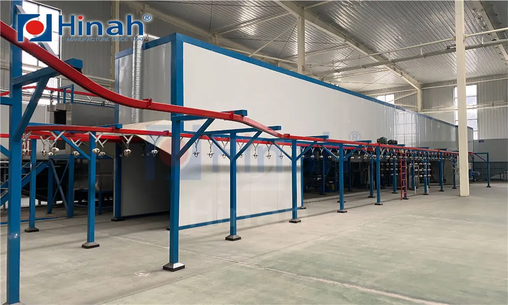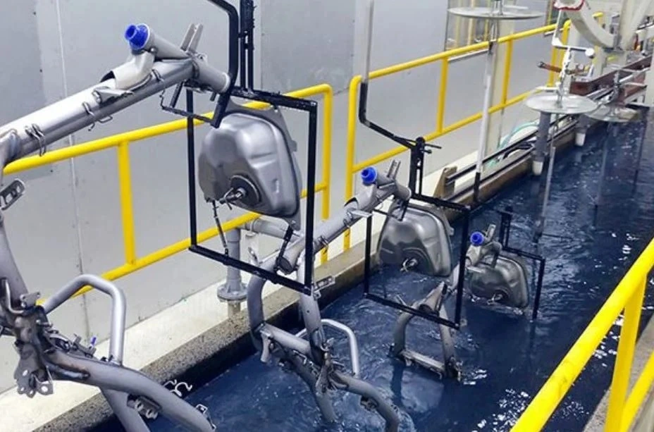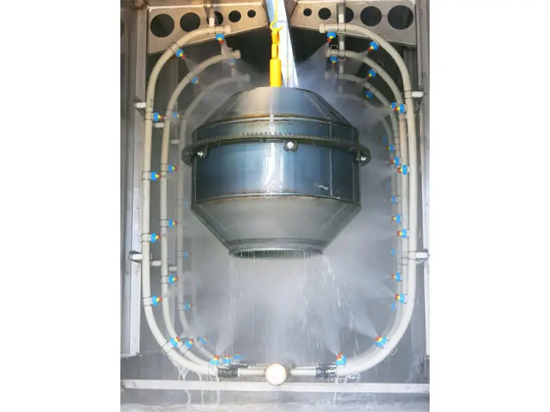
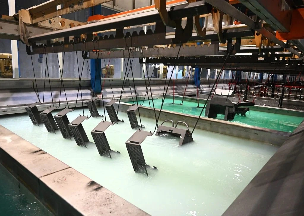
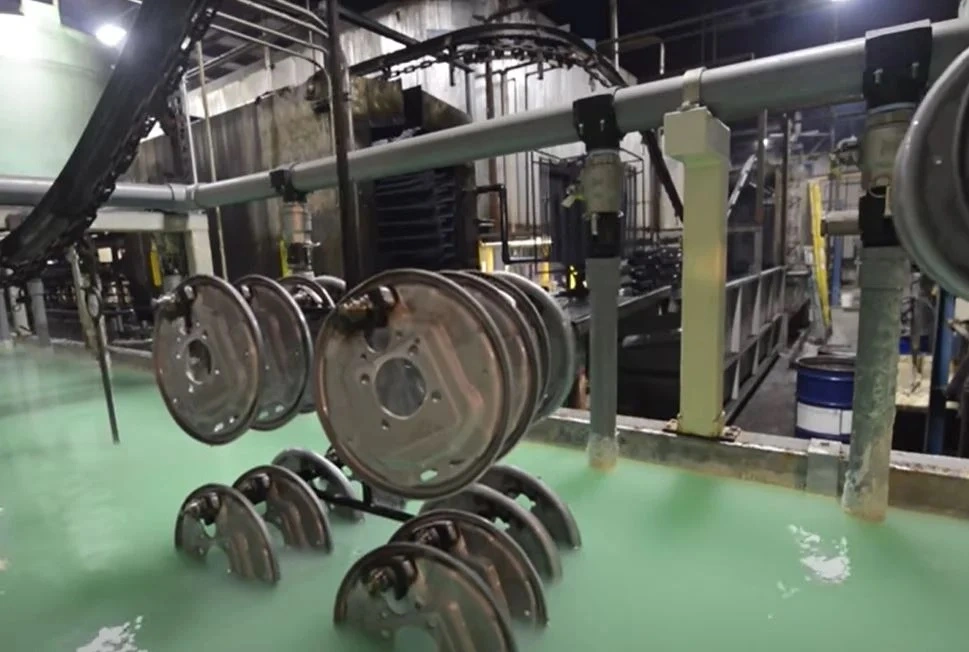
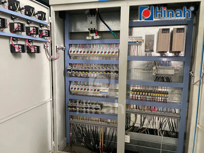
Surface finishing productivity depends heavily on the continuous, synchronized movement of workpieces across multiple rigorous environments. In automated production environments, powder coating conveyor systems serve as the kinematic backbone connecting surface preparation, chemical pre-treatment dry-off, electrostatic application booths, and high-temperature curing ovens into an unbroken manufacturing sequence. Specifying the incorrect transport mechanism creates chronic assembly bottlenecks, contamination issues, and premature mechanical breakdown due to demanding thermal cycling and aggressive chemical exposure.
Achieving peak operational equipment efficiency demands a comprehensive understanding of conveyor mechanics, metallurgical tolerances, chain dynamics, and thermal expansion phenomena. Whether dealing with high-mix automotive brackets or structural steel fabrications spanning several meters, modern coating infrastructure requires purpose-built conveyance mechanisms engineered to maintain line continuity under continuous thermal, mechanical, and electrostatic loads.
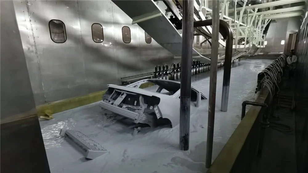
Every industrial finishing line demands a specific balance between continuous flow, load density, process timing, and footprint economy. Mechanical engineers classify industrial conveyance options based on chain retention, drive architecture, and rail structural profiles.
Continuous monorail overhead conveyors represent the most traditional and cost-effective method for standardized finishing runs. Built with a continuous loop of chain suspended inside or under an structural steel track, these units cycle through pre-treatment, spray zones, and curing ovens at a uniform, fixed or variable drive speed.
Enclosed Track Systems: Utilizing a rolled-steel tube that fully encloses the universal-link chain, this configuration shields the internal bearings from particulate fallout and prevents residual lubricants from dripping onto raw workpieces. Enclosed track solutions operate efficiently with lighter to medium payload profiles, typically up to 50 kg per suspension point, utilizing tight horizontal and vertical turn radii to conserve real estate in compact plant layouts.
Drop-Forged I-Beam Systems: Built upon heavy structural steel I-beams (commonly 3-inch, 4-inch, or 6-inch profiles such as X348, X458, or X678 drop-forged chains), these units support significant structural masses ranging from hundreds of kilograms to multiple metric tons per load bar. The open-track nature requires aggressive shield baffling to prevent lubricant contamination within chemical mist zones and baking sections.
When the finishing sequence involves disparate cycle times—such as complex manual masking, robotic spray zones requiring part indexing, and prolonged oven baking—standard continuous monorails encounter operational limits. Power and free configurations solve this throughput mismatch by separating dynamic drive power from load movement.
The system utilizes two distinct tracks within a single vertical envelope: an upper "power" track housing a continuously moving pusher chain, and a lower "free" track where wheeled load trolleys navigate independently. Spring-loaded or mechanical pusher dogs engage the trolley assemblies, pulling them along the route. By incorporating mechanical stops, track switches, and bypass spurs, power and free systems allow automated accumulation, offline buffering, variable line speeds per zone, and localized elevation changes without interrupting the broader plant cadence.
When finish specifications require an absolute absence of overhead contamination, inverted floor-mounted tracks relocate the drive chain, guide rails, and wear components directly beneath the workpieces. Workpieces mount onto vertical fixtures extending upward from the base trolley. This topology protects pristine surfaces from falling particulate, oil droplets, and chain-wear debris, making it common in high-tier industrial and electronic enclosures requiring optical-grade powder coverage.
A conveyor line traversing chemical washers, drying zones, and 220°C curing chambers experiences brutal environmental extremes. Engineering these systems requires selecting components suited for severe duty cycles.
Within the curing chamber, metal temperatures frequently hover between 180°C and 250°C for durations extending past 30 minutes. Unhardened mild steel links experience severe yield degradation and accelerated elongation at these temperatures. Chains designed for industrial powder finishing utilize drop-forged, heat-treated carbon-manganese or micro-alloy steels featuring surface-hardened pins and open-link architectures designed to shed powder accumulation.
Bearing selection dictates uptime. Shielded bearings with high-temperature carbon-graphite cages or full-complement ceramic balls eliminate traditional grease breakdown. Where liquid lubrication remains mandatory, synthetic perfluoropolyether (PFPE) formulations resist vaporization and cracking, preventing the dreaded "carbonization" that locks up conveyor wheels inside curing zones.
Kinematic stability relies on maintaining continuous chain tension despite significant thermal fluctuations. Structural steel expands substantially inside ovens; a 100-meter track section running from an ambient 20°C ambient room to a 200°C curing zone experiences measurable physical growth. Without proper tension absorption, chain links bunch up at entry transitions, leading to drive motor overload and track binding.
Pneumatic or counterweighted dynamic take-up units continuously absorb chain slack. In multi-drive layouts common to long runs, industrial variable frequency drives (VFDs) coordinate caterpillar drive motors through closed-loop encoder feedback. Load monitoring across drives ensures horsepower sharing, avoiding uneven link stretch across expansive production perimeters. Engineering teams at HANNA configure take-up units with responsive pneumatic tracking to offset these severe thermal variations without triggering emergency motor overcurrent shutdowns.
Maximizing coating transfer efficiency requires the continuous clearance of components through process tunnels. Horizontal and vertical curves must clear the maximum envelope of the longest, widest part swung on an operational pitch. Calculating the true path involves analyzing horizontal sweep angles on curves and vertical drop limitations where parts pitch downward into pre-treatment entry zones.
Specifying oversized turn radii minimizes lateral thrust forces against track walls, reducing mechanical wear on trolley side-guide rollers. In heavy-duty lines, hardened track inserts reinforce high-stress horizontal curves to counter localized structural fatigue.
Integrating powder coating conveyor systems requires a deep evaluation of thermal mass, environmental separation, and grounding reliability. Overlooking these factors damages line capacity and surface quality.
Every kilogram of steel represented by trolley hardware, load bars, chains, and suspension racks acts as a thermal heat sink. When the conveyor passes from the application booth into the curing chamber, these heavy steel members draw thermal energy away from the actual product. This parasitic heat loss forces burner systems to fire continuously at higher capacities, increasing operating utility costs.
Designers combat this inefficiency through lightweight, high-yield alloy tooling and optimized hook-to-part ratios. Reducing jig tare weights while maintaining structural rigidity allows lower oven setpoints, faster heat-up rates, and accelerated line speeds, drastically expanding active curing throughput within a given oven footprint.
The chemical washing stages create humid, steam-laden atmospheres containing acidic or alkaline cleaners, followed immediately by water rinses. When chain sections exit pre-treatment, trapped moisture can cause surface oxidation and wash away pin lubricants. Entering the powder booth with wet or improperly lubricated chains leads to two distinct failure modes: mechanical squeal and bearing seizure from unlubricated contact, or airborne lubricant droplet ejection onto unbaked powder, creating surface craters and pinholing.
To mitigate this operational vulnerability, high-end finishing architectures install continuous hot-air moisture blow-off dry tunnels immediately preceding the powder enclosure. Automated, micro-shot shot lubricators discharge microscopic, metered droplets of synthetic grease directly to critical chain articulation pins outside the spray enclosure, ensuring mechanical lubrication without oversaturating the links.
Electrostatic powder application demands that the targeted metal component maintain a clean electrical pathway to ground (resistance under 1 megohm according to NFPA standards). As parts hang from hooks and swivels, repeated cycling through powder spray zones layers cured polymer film directly onto the attachment contacts. Once non-conductive powder coats the load hooks, the electrical ground pathway breaks.
Loss of ground produces back-ionization, poor wrap-around coverage, reduced transfer efficiency, and massive powder waste. Conveyor system hooks should integrate hardened steel knife-edge contact profiles that bite mechanically through residual coatings, paired with routine chemical, burn-off, or cryogenic jig stripping routines.
Specifying powder coating conveyor systems requires balancing dynamic line loads, operational speeds, and thermal exposure times. Calculating baseline operational variables correctly safeguards the long-term throughput capacity of the complete manufacturing cell.
The baseline sizing calculation links desired annual throughput to component loading pitch and required curing time. The governing kinematic equation is straightforward:
Line Speed (meters/minute) = [Required Part Output per Hour × Component Pitch (meters)] / [60 × Loading Efficiency Factor]
Once line speed is determined, the physical length of the curing oven chamber reflects the thermal requirement:
Minimum Heated Oven Length (meters) = Line Speed (meters/minute) × Required Dwell Time at Metal Temperature (minutes)
Failing to factor in component warm-up lag—the time needed for dense core metal to reach cross-linking temperature prior to starting the cure countdown—leads to chronically under-cured finishes or forces plants to drop line speeds far below design capacity.
As the conveyor system runs through multi-stage wash stages (degreasing, phosphating, zirconium deposition, reverse-osmosis rinses), aggressive chemical vapor must not migrate into the tracking system or downstream powder spray booths. Conveyor slots cut into tunnel roofs require effective fluid dynamic isolation.
Industrial layouts use high-efficiency air seals, positive-pressure clean air blowers, and mechanical neoprene or silicone slot wipers along the conveyor slit. Stainless steel (AISI 304 or 316) track sections are mandatory directly above wet pre-treatment stages to avoid the chronic structural flaking seen when standard painted carbon steel suffers chemical corrosion.
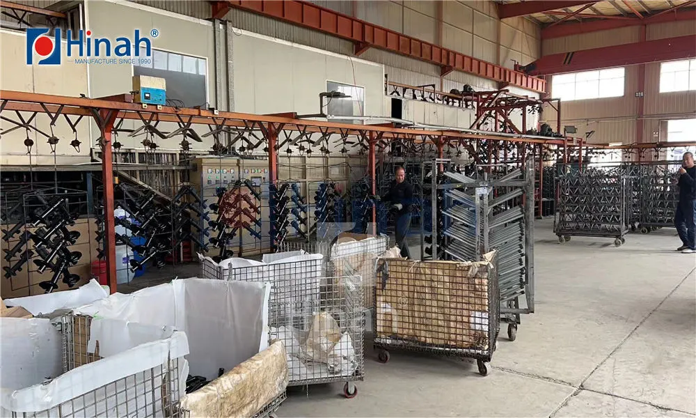
Preventive maintenance on industrial conveyance mechanisms protects capital investments and keeps lines operating at peak efficiency. Neglecting mechanical wear along elevated track networks leads to unexpected chain partings and costly production stops.
| Subsystem | Inspection Frequency | Critical Parameter / Metric | Corrective Action |
|---|---|---|---|
| Drive Caterpillar | Monthly | Drive dog wear, shear pin condition, drive chain deflection | Realign drive dogs, adjust tension to manufacturer spec, replace worn dogs |
| Overhead Chain | Bi-weekly | Elongation check (>3% over 10 links denotes critical fatigue) | Take up chain slack; rebuild worn segments if elongation exceeds parameters |
| Trolley Bearings | Weekly | Rotational resistance, excessive play, sound profiling via ultrasound | Clean bearing races, cycle high-temp lubricant, replace seized units |
| Expansion Joints | Quarterly | Structural overlap gap inside high-temperature oven transitions | Clear thermal slider binding, verify free floating movement |
| Take-Up Cylinders | Weekly | Air pressure regulation, linear travel buffer reserve | Adjust baseline pressure; replenish stroke capacity to compensate for wear |
System integrators like HANNA prioritize robust service accessibility across all drive modules, engineering drop-out track sections and modular lubrication junctions to streamline these necessary inspections. Proactive ultrasonic analysis of trolley bearings inside active dry-off and curing ovens identifies structural friction points long before catastrophic mechanical binding occurs.
Enclosed track conveyors feature a lower structural profile and contain moving components internally, which prevents lubricant drops onto raw parts. However, they reach structural limits around 50 kg to 100 kg per hook point. For massive industrial castings or dense structural beams exceeding these parameters, I-beam systems (such as 3-inch or 4-inch structural profiles) are mandatory due to their heavy load capabilities, high tensile drop-forged chains, and elevated shear limits.
As the conveyor track and chain enter an oven operating at 200°C, the steel expands relative to the cooler exterior ambient tracks. This creates localized chain slack at the oven exit. Without dynamic, continuous pneumatic or counterweighted take-up systems, this slack causes chain buckling, surge patterns, or track jumping at downstream drive sprockets.
Modern powder coating conveyor systems often deploy hardened knife-edge hanging fixtures that bite through minor overspray build-up to establish metal-to-metal continuity. In addition, production lines incorporate inline grounding brush contacts that ride along bare copper bars tied to earth rods, complemented by routine mechanical burn-off, fluid bed stripping, or blasting cycles for parts racks.
Cross-contamination is managed using slot exhaust air seals above the wash tunnels, physical baffle zones between process enclosures, and dedicated dry-off ovens directly following final rinses. The dry-off stage heats both the parts and the carrying hardware, evaporating residual water droplets lodged inside chain links or suspension hooks before they enter the electrostatic application zone.
Select continuous monorail systems when workpieces share uniform geometry, consistent spray patterns, identical curing dwell requirements, and uninterrupted movement. Select power and free systems if the production run involves variable part sizes, selective offline manual operations, robotic holding cells, or vertical switching tracks that accumulate parts inside compact, multi-pass curing ovens.
Automatic lubricators should cycle based on operational hours and chain speed rather than arbitrary calendar dates. In standard two-shift operations traversing elevated curing temperatures, micro-shot systems cycle every 40 to 60 operating hours, targeting minute amounts of high-temperature synthetic fluid to critical friction points without creating surplus residue that could contaminate components.
Optimizing finishing productivity demands tailored machinery built around exact spatial, structural, and chemical parameters. The selection and deployment of bespoke powder coating conveyor systems requires an integrated assessment of total payload weights, process chemistry, line speeds, and spatial track layouts. Technical specialists evaluate conveyor geometries, chain metallurgy, and structural loading margins to construct finishing platforms built for multi-decade duty cycles.
Whether modernizing an existing overhead track to eliminate line surging or engineering a multi-stage, high-capacity finishing system from the ground up, partner with verified industry engineers. Provide your part envelopes, weight specifications, chemical pre-treatment stages, and target production volumes to the engineering team atHANNA to receive a detailed system layout, thermodynamic load calculation, and comprehensive technical quotation.